What’s the latest on the BackYarder structure development?
Space Craft Systems recently completed an important milestone towards producing their first completed building – the BackYarder prototype home.

We went to a local company, fed their computer with a two-dimensional map of 70 items and their cutting machine (a CNC router) with a full sheet of structural plywood, and left the two together for a couple of hours. What came out the other end was 70 pieces of plywood of varying sizes, plus a bag of sawdust. All of the pieces fitted together in some way or another like one of those bizarre wooden puzzles you get as a Christmas present – and can never get back together again. Whichever way you look at them, they certainly don’t look like a house. Even for many of the team here who work on the project day-to-day, it can be hard to grasp the significance of this event.

Our General Manager, Jane Webb, recently asked me to try and convey some of the complexity and sheer hard work that goes into getting to the stage we’re currently at, and to explain how a test cut like this fits into the larger picture of producing a significantly different construction system from the way we currently go about creating our built environment.
The Matrix...
There’s a quite extensive back-story to this test cutting exercise which explains why this was significant. Not least, this was the first time we were using a partner in our home city of Christchurch to do the cutting (all the previous cutting had been done in Wellington or overseas), and the first time in two years we started cutting new building components. That it has taken two years to get to this point gives some indication of the huge amount of preparatory groundwork that has been required.
Initial design work
The designs of those small parts have a long history, way longer even than the whole WikiHouse project. For example, the dovetail lengthening joints are to be found in furniture entombed with mummies dating from the First Dynasty of ancient Egypt. Part of the design work involved in WikiHouse has been adapting these joints so they can be cut by a computer-controlled production machine, which in turn means we can re-introduce some of this ancient design technology that has been lost from most other modern construction techniques.
Design development
In other cases, we’ve invented new joinery construction which we’ve not seen used anywhere else in the world. We haven’t done this for the sake of doing something neat (although we do think the forms have a certain functional and aesthetic beauty to them). Rather, the form of each piece follows a collection of functions arising from the specific design challenges we’ve set ourselves on the path to a much higher performance house at a more affordable price. Specific engineering considerations are reflected in all of these component parts, but also considerations around economy of materials (environmental impact and lowering costs), ease and speed of construction (empowering people and streamlining production), adaptability (enhancing utility), and strength (safety and resilience), to mention but a few.

Each of the parts in that test cut build on lessons learned from other more recent projects which have evolved over the last ten years or so. They are inspired by, or build on ideas from, projects such as instantSHELTER and yourHOUSE (headed by Professor Larry Sass at Massachusetts Institute of Technology). They also represent the culmination of knowledge gained so far in the multiple WikiHouse prototypes built around the world over the last few years.
So that single cutting test embodied something like 50 improvements from the previous one; not a single one of those 50 or so component s and sub-components went into this test without at least two improvements from the last time we cut it. Since we cut our last proof-of-concept structure, we’ve also switched to more capable 3D modeling software, so the whole library of parts has been remodeled more accurately in a different format. To date, this has resulted in over 120 new 3D CAD models as we have steadily drawn up components and improved them. Together, the pieces in the cutting test represent around 90% of all the components that will come together to build the entire structural kit needed to produce a whole range of buildings, whether for residential, commercial or community use.
The test cut also permitted us to test and optimise a whole range of manufacturing settings, such as the type of cutter that is optimal for our needs, tolerances between different parts, nesting efficiency, cutting speed, improvements to reduce production time and machine wear, and so on.
Story of a humble peg
A good illustration of the extensive thinking and groundwork that has occurred is to look at the design of a single, humble wooden peg, which is currently the main method used to hold the structure together.
The use of tapered wooden pegs undoubtedly pre-dates almost any other component in the design, including the dovetail joints which date back to early dynasties of the ancient Egyptians. This seemingly simple component is the result of a significant number of design decisions during the short history of WikiHouse. Space Craft Systems and WikiHouseNZ are now on their fourth generation of peg (with three current variations). Each one of those builds on the original design created by the UK WikiHouse project founders, which in turn references the use of tapered wooden pegs in construction and boat-building which stretches back at least 2600 years. The WikiHouse peg design started life 95mm long, with a 4.7 degree taper, a 19mm ‘head’ and a 76mm long ‘body’. They were initially designed to be used one at a time to secure the main components and take up slack across the structure.
However, we found that just using a single peg, as they were driven home they bit into the adjacent parts and slack was taken up diferentially along their length. In some cases this encouraged the frame elements to move out of alignment. Our latest peg types are now designed to work as a pair. This has significantly reduced the way they cut into neighbouring parts (which in turn improves the number of times a frame can be taken apart, changed, repaired or moved without degrading its performance), and any slack gets taken up in parallel (which means the frame tightens up much more predictably and consistently).
The current pegs are now a little longer at 135mm, which enables us to secure more components at once and to better secure the pegs themselves. This also adds a greater ability to take up slack across the frame, which in turn permits us to accommodate greater variation when manufacturing the structural sheet materials used in the frame, along with expansion and contraction due to variations in moisture content and temperature. Increasing the peg length a little also permitted us to remove a small notch which had helped cut a sharper corner at the head but slowed production.
The peg width has been adjusted as these are designed deliberately to be the weakest components in the main construction joints, since they are easily replaced at low cost. Under extreme loads (for example a significant earthquake event), the pegs are designed to fail in a controlled manner before the neighbouring structural elements, avoiding damage to the main beams and connectors.
We’ve also refined the angle between shaft and head, which is critical in achieving the optimal balance of mechanical advantage alongside useful capacity to take up slack. Too low an angle means there is a lot of mechanical advantage – the result is that you may well burst the joint. Plus there is a lot of travel to achieve only a moderate tightening of the frame, and pegs get very hard to retrieve if you ever want to take them out. Too high an angle means the pegs don’t tighten up progressively – either the peg is loose or fully tight, with nothing in-between. The mechanical advantage is also quite low, so you have to hit the peg much harder to take up slack in the frame.
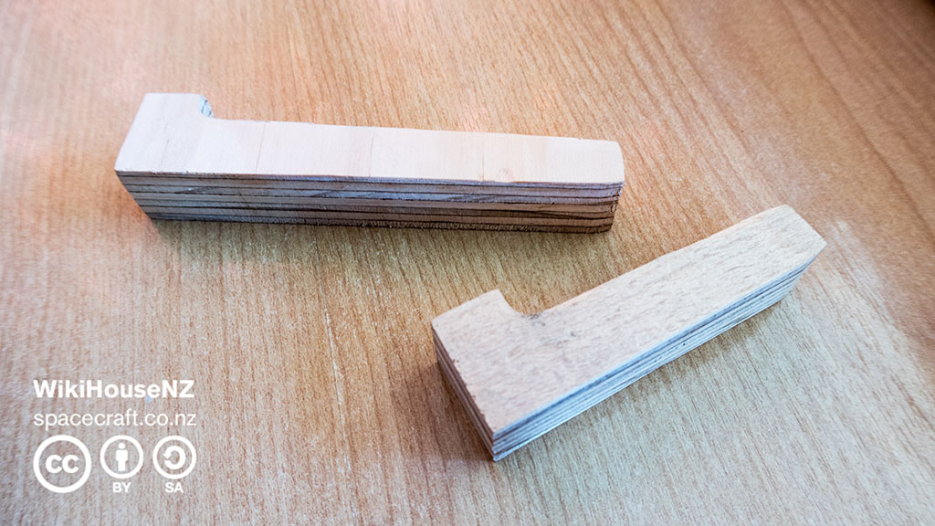
We cut a small distinctive ‘head’ on each peg so there’s a distinctive shape for a pair when in-situ. This helps users install them correctly and makes it easier to strike the peg home. In the latest design, we made the head a little smaller, since this sometimes fouled the edge of adjacent components when being installed. We have also removed a small notch in the head, commonly called a ‘dogbone’, which was originally added to enable the round cutting bit on the manufacturing machine to cut a sharp junction between peg and building. We found we didn’t need the notch once we redesigned the pegs to work in pairs and had added the taper to the ends of them. And removing the notch both improves speed of production and gives the pegs a stronger head.

Image shows an example of pegs in use, with distinctive opposing heads when installed correctly.
To make changes in design and variations easier to implement in future, we changed the point at which the peg is centred in our 3D computer-aided design software. This will allow us to update hundreds of pegs throughout a single building in future through adjustments to just one master file.
We introduced an additional small taper at the tip of the peg, as previously the square ends sometimes caught on the veneers of ply, damaging the components they were securing. This small taper also makes it easier to locate the pegs in the peg holes, in turn making construction easier and more enjoyable.

Each of these design features start off as hand-drawn or computer-aided design (CAD) sketches – simple concepts first of all and then more detailed development sketches – which are then translated into accurate 3D CAD models, in both two and three dimensions. From these, two-dimensional cutting profiles are exported, which are then copied and ‘nested’ on the final production cutting sheet. Alongside the 3D modeling, we also need to maintain and update our documentation so that in future others can build from our efforts when helping to develop the system.
The tip of the iceberg
Although quite extensive, the story around the peg is just the tip of the iceberg regarding the full range of things which needed to be put in place for that successful test cut to come out the other end. Here are some of the others that were undertaken:
Since no-one currently uses structural plywood in the same way that we do, the specifications which govern structural plywood aren’t particularly relevant to ensuring it will perform in the way we’re using it. This essentially means we need to self-certify a particular plywood product from a particular manufacturer. So in order for our test cut to give us the information we needed, it was crucial to establish a relationship with a timber industry partner who was interested in exploring a longer-term relationship. The test cut allowed us to rigorously assess the manufacturing standards of the plywood we plan to use for production. We were able to assess stated material thickness against actual, plus quality of the veneers and the way they were put together. In this case results were very encouraging.
The companies doing the production don’t have capacity to store our materials, so we have needed to find our own space. This is one of the roles played by our own housing innovation laboratory, the WikiLab, a factory space where we have installed storage racking.
As we’re not currently running our own production machinery, we have needed a van to carry materials. Initially we negotiated use of a van from a local community organisation, and more recently secured our own.
In order to get reliable test results from our test production that will satisfy ourselves and the regulatory authorities, we need access to accurate testing equipment and test rigs. Constructing your own takes time, experience and can be expensive. Using third-party test facilities can be much quicker but very costly, well beyond our current budget resources. This has meant spending time developing a relationship with people who have access to those test facilities. Getting good review and validation of our ideas also means recruiting help from experienced professional engineers. Again, we don’t have the resources to pay these professionals so we need to enthuse them about the social and environmental aims of the project and the values that drive our company.
To work effectively and collaboratively as a team of largely volunteers, many working in separate locations, we are developing file sharing and communication systems, along with task and project management.
So what comes next?
The test pieces have spurred conversations around design improvements within our own team and with external consultants. The Space Craft design team have taken the lessons from that first test cut and fed them back into another improved set of components, resulting in a new set to be cut in the near future. From this will come a more ambitious set of pieces that can be assembled into a complete section of the building frame. This will include a couple of short structural beams that we can use for the first round of laboratory structural testing. The results of that will permit our engineers and design team to build and test the most critical parts of the whole structure at full size. This will include a long test beam – currently just over 7.6m long – which includes critical corner elements, the connection between the main structural frame elements and a beam which will be longer than any clear span in the current design.
Over the last few months we've made good progress and we're now starting to get a 'lean' workflow working again – cutting test pieces, feeding the lessons learned and improvements back quickly into the next design iteration and then cutting something a bit bigger and more ambitious next time around, with a clear pathway through to the first fully finished building over the next few months.